Digital Electronics Complete Guide - Number Systems, Logic Gates, K-Maps & Boolean Algebra
By Chetan Sharma · · Updated · 6 min read
Digital Electronics: Complete Study Guide
Introduction to Digital Electronics
Digital electronics forms the foundation of modern computing systems, from smartphones and laptops to embedded systems and microcontrollers. Unlike analog systems that work with continuous signals, digital electronics uses discrete states (typically 0 and 1) to represent, process, and transmit information. This fundamental difference enables reliable, noise-resistant communication and complex computational operations.
Understanding digital electronics is essential for anyone pursuing careers in:
- Computer Engineering: Design CPUs, memory, and digital circuits
- Embedded Systems: Develop IoT devices, microcontroller applications
- VLSI Design: Create integrated circuits and chip architectures
- Electronics Engineering: Build digital communication systems
- Software Development: Understand hardware-software interaction
What You'll Master in This Guide:
- Analog vs digital signal characteristics and comparisons
- Number systems including binary, octal, decimal, and hexadecimal
- Binary arithmetic operations and code conversions
- Logic gates and universal gates (NAND/NOR)
- Boolean algebra postulates and simplification techniques
- Sum of Products (SOP) and Product of Sums (POS)
- Karnaugh Map (K-Map) simplification methods
Download Comprehensive Study Materials
Access detailed assignments and unit-wise notes covering all digital electronics topics:
1. Analog vs Digital Signals - Key Differences
Understanding Signal Types
Analog Signals:
- Continuous waveforms with infinite possible values
- Vary smoothly over time without discrete jumps
- Examples: temperature variations, sound waves, radio signals
- Used in traditional audio systems, thermometers, speedometers
- Susceptible to noise and signal degradation over distance
Digital Signals:
- Discrete states with finite number of values (typically 0 and 1)
- Abrupt transitions between voltage levels
- Examples: computer data, digital audio (MP3), digital video
- Used in computers, smartphones, digital cameras, modern communication
- Robust against noise, easily processed and stored
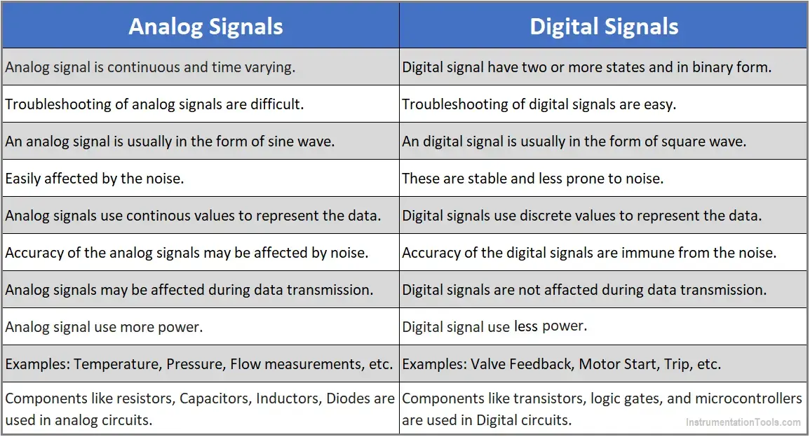
Comparison Table:
| Feature | Analog Signal | Digital Signal |
|---|---|---|
| Nature | Continuous | Discrete |
| Values | Infinite | Finite (0 and 1) |
| Accuracy | Lower | Higher |
| Noise Immunity | Poor | Excellent |
| Storage | Difficult | Easy |
| Processing | Complex | Simple |
| Bandwidth | High | Low |
| Examples | Radio, TV broadcast | Computers, smartphones |
2. Number Systems - Understanding Different Bases
Number systems are mathematical notations used to represent quantities. Different bases suit different applications - decimal for humans, binary for computers, hexadecimal for programming.
1. Decimal Number System (Base 10)
- The decimal system is the most commonly used number system in everyday life. Each digit's position represents a power of 10.It uses 10 distinct values 0,1,2,3,4,5,6,7,8 and 9. hence it's radix is 10.
- Digits: 0-9 (10 distinct symbols)
- Base/Radix: 10
- Position Values: ...10³, 10², 10¹, 10⁰
- Example: 245₁₀ = (2 × 10²) + (4 × 10¹) + (5 × 10⁰) = 200 + 40 + 5
- Use Cases: Everyday calculations, financial transactions, measurements
2. Binary Number System (Base 2)
- The binary system is used primarily in computing and digital electronics. Each digit's position represents a power of 2.This system uses only two symbols 0 and 1. Hence it's base or radix is 2.
- Digits: 0 and 1 (2 distinct symbols)
- Base/Radix: 2
- Position Values: ...2³, 2², 2¹, 2⁰
- Example: 1011₂ = (1 × 2³) + (0 × 2²) + (1 × 2¹) + (1 × 2⁰) = 8 + 0 + 2 + 1 = 11₁₀
- Use Cases: Computer memory, processors, digital circuits, programming
3. Octal Number System (Base 8)
- The octal system is sometimes used in computing as a shorthand for binary. Each digit's position represents a power of 8. This system uses 8 distinct symbols. 0,1,2,3,4,5,6 and 7. Hence it' radix is 8.
- Digits: 0-7 (8 distinct symbols)
- Base/Radix: 8
- Position Values: ...8³, 8², 8¹, 8⁰
- Example: 24₈ = (2 × 8¹) + (4 × 8⁰) = 16 + 4 = 20₁₀
- Use Cases: Unix file permissions, assembly programming
4. Hexadecimal Number System (Base 16)
- The hexadecimal system is commonly used in programming and computer science as a compact way to represent binary data. Each digit's position represents a power of 16.It uses 16 values to represent data. 0,1,2,3,4,5,6,7,8,9,10,11,12,13,14 and 15. Hence it's radix is 16.
- Digits: 0-9, A-F (16 distinct symbols where A=10, B=11, C=12, D=13, E=14, F=15)
- Base/Radix: 16
- Position Values: ...16³, 16², 16¹, 16⁰
- Example: 2F₁₆ = (2 × 16¹) + (15 × 16⁰) = 32 + 15 = 47₁₀
- Use Cases: Color codes (#FF5733), memory addresses, MAC addresses
3. Number System Conversions and Binary Arithmetic
3. Conversion of number systems,Binary Arthematics, Gray code, Excess 3 code and BCD code
Number System Conversions
Decimal to Binary Conversion (Successive Division Method):
- Divide number by 2 repeatedly
- Record remainders in reverse order
- Example: 13₁₀ → 13÷2=6 R1, 6÷2=3 R0, 3÷2=1 R1, 1÷2=0 R1 → 1101₂
Binary to Decimal Conversion:
- Multiply each bit by 2 raised to its position
- Sum all products
- Example: 1101₂ = (1×8) + (1×4) + (0×2) + (1×1) = 13₁₀
Binary Arithmetic Operations
Addition:
  1011  (11)
+ 0110  ( 6)
-------
 10001  (17)
Rules: 0+0=0, 0+1=1, 1+0=1, 1+1=10 (carry 1)
Subtraction:
  1011  (11)
- 0110  ( 6)
-------
  0101  ( 5)
Special Codes
BCD (Binary Coded Decimal):
- Each decimal digit encoded as 4-bit binary
- Example: 29₁₀ → 0010 1001 (BCD)
- Used in digital clocks, calculators
Gray Code:
- Only one bit changes between consecutive numbers
- Reduces errors in analog-to-digital conversion
- Example: 0000, 0001, 0011, 0010, 0110, 0111...
Excess-3 Code:
- BCD + 3 (self-complementing code)
- Example: 5₁₀ → 0101 (BCD) + 0011 → 1000 (Excess-3)
These topic will be complex...
I prefer to read the first pdf so that you can understand these because these contains lots of formulas and calculations.
4. Logic Gates - Building Blocks of Digital Circuits
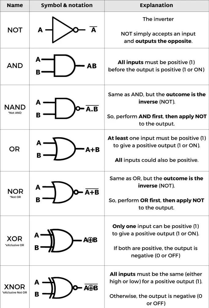
Logic gates are fundamental digital circuit elements that perform Boolean operations on one or more binary inputs to produce a single binary output. They form the foundation of all digital systems including processors, memory, and controllers.
Basic Logic Gates:
1. AND Gate
- Output is 1 only when ALL inputs are 1
- Symbol: A · B or A ∧ B
- Truth Table: 00→0, 01→0, 10→0, 11→1
- Application: Enable/disable signals, security systems (all conditions must be true)
2. OR Gate
- Output is 1 when AT LEAST ONE input is 1
- Symbol: A + B or A ∨ B
- Truth Table: 00→0, 01→1, 10→1, 11→1
- Application: Alarm systems, parallel switches
3. NOT Gate (Inverter)
- Output is opposite of input
- Symbol: A' or Ā or ¬A
- Truth Table: 0→1, 1→0
- Application: Signal inversion, complementing
4. NAND Gate (Universal Gate)
- AND followed by NOT (opposite of AND)
- Output is 0 only when ALL inputs are 1
- Truth Table: 00→1, 01→1, 10→1, 11→0
- Universal: Can create any other logic gate
5. NOR Gate (Universal Gate)
- OR followed by NOT (opposite of OR)
- Output is 1 only when ALL inputs are 0
- Truth Table: 00→1, 01→0, 10→0, 11→0
- Universal: Can create any other logic gate
6. XOR Gate (Exclusive OR)
- Output is 1 when inputs are DIFFERENT
- Symbol: A ⊕ B
- Truth Table: 00→0, 01→1, 10→1, 11→0
- Application: Adders, parity checkers, comparators
7. XNOR Gate (Exclusive NOR)
- Output is 1 when inputs are SAME
- Symbol: A ⊙ B
- Truth Table: 00→1, 01→0, 10→0, 11→1
- Application: Equality checkers, error detection
5. NAND and NOR Gates as Universal Gates
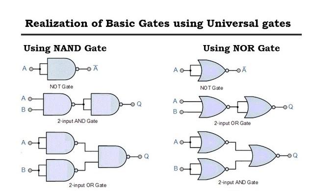
5. NAND and NOR gate as universal gate -
NAND and NOR gates are called universal gates because you can use them to create any other type of logic gate, including AND, OR, and NOT gates.
6. Posulates of Boolean Algebra
A statement that is not proved but assumed as true is called posulates. Some of the rules are :
- Commutative Law
- A+B = B+A
- A.B = B.A
- Associative Law
- (A+B)+C = A+(B+C)
- (A.B).C = A.(B.C)
- Distributive Law
- A(B+C) = AB + AC
- A + BC = (A+B). (A+C)
- Identity Law
- A+A=A
- A.A = A
- Absorption Law
- A + A.B = A
- A.(A+B) = A
- Complement rule
- A + A' = 1
- A * A' = 0\
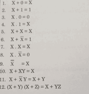
some basic rules are :
7. SOP AND POS
- SOP :
- It is one of the ways of writing a Boolean expression. As the name suggests, it is formed by adding (OR operation) the product terms. These product terms are also called as ‘min-terms’. Min-terms are represented with ‘m’, they are the product(AND operation) of Boolean variables either in normal form or complemented form.
- POS :
- As the name suggests, it is formed by multiplying(AND operation) the sum terms. These sum terms are also called as ‘max-terms’. Maxterms are represented with ‘M’, they are the sum (OR operation) of Boolean variables either in normal form or complemented form.
8. K map
here the king comes, this is the simple and most important topic of the syllabus.
What it is?
This is the visual representation of the expression in this we can easily represent the logical expression in blocks. the structure is:
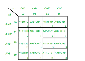
thank you, I hope thse notes will help you to understand topics.